What Is PVAlign? Interactive Solar Panel Simulator Guide
Explore PVAlign's interactive solar power simulator, including PV, battery, inverter, SPD surge testing, grounding, wiring, protection, measurement, and household appliance nodes.
Guide · August 11, 2026 · 37 min read
PVAlign is a free, browser-based interactive solar panel simulator and learning platform. It lets you place electrical components on a visual canvas, connect their terminals, edit their ratings, and study how power moves through a photovoltaic system. Instead of reducing a design to one daily-energy number, PVAlign represents panels, controllers, batteries, inverters, conductors, protection devices, meters, and loads as connected nodes.
That node-based approach makes PVAlign useful for learning questions such as:
- What changes when solar panels are wired in series, parallel, or a series-parallel array?
- Why does an MPPT charge controller usually harvest more power than a PWM controller from a high-voltage panel?
- Can the battery bank accept all the charging current available from the array?
- How much DC current must a battery supply to run an AC appliance through an inverter?
- What happens when a 50 Hz-only appliance receives 60 Hz, or a hybrid inverter connects to a grid with a different frequency?
- How does an automatic transfer switch move one AC load between qualified normal and emergency sources without paralleling them?
- How does a Type 2 surge protective device divert an 8/20 microsecond test impulse through a modeled protective-earth path?
- Why do a kettle and rice cooker lose heating power as voltage falls while a television or laptop adapter tries to maintain constant power?
- How do conductor size, length, material, ambient temperature, and installation method affect voltage drop and heat?
- What happens when a breaker or low-voltage disconnect is undersized, a load receives the wrong supply type, or a PV input exceeds its voltage rating?
- How does an SPDT relay move a load between normally closed and normally open contacts when its isolated coil energizes?
- How does a DC contactor use a low-current control circuit to switch a higher-current DC load circuit?
PVAlign is designed for solar education, system comparison, and preliminary planning. It is not a product-selection certificate, permitting tool, or replacement for a qualified designer.
Start Here
Try PVAlign in 2 Minutes
- Openthe simulator
- Loadthe Off-Grid preset
- Changesolar irradiance
- Inspectthe PV watts
- Adda compatible load
How the PVAlign solar simulator works
A PVAlign circuit has three main layers:
- Nodes represent electrical equipment, sources, storage, instruments, protection, and loads.
- Wires and junctions define the electrical topology. A crossing is not a connection unless a junction is created.
- The simulation engine resolves an estimated steady-state operating point and returns voltage, current, power, losses, operating state, and warnings to the canvas and inspectors.
You can click a part to place it near the center of the canvas or drag it to a chosen position. Click one terminal and then another compatible terminal to create a conductor. Clicking an existing wire while making a connection creates a real branch junction; simply drawing one wire across another keeps the circuits separate.
The simulator validates connections before adding them. It checks terminal polarity, AC/DC compatibility, voltage classes, battery chemistry, duplicate connections, single-source load rules, invalid PV loops, battery-bank loops, breaker type, and other topology constraints. Some unusual but solvable circuits are allowed with warnings, while clearly incompatible or dangerous connections are rejected.
Current PVAlign nodes at a glance
PVAlign currently provides 28 user-addable equipment types. The following table uses the same SVG equipment illustrations shown by the current simulator. The small terminal circles on the canvas are the connection points that make each illustrated component an electrical node.
| Node | Current simulator illustration | Purpose |
|---|---|---|
| Solar panel | 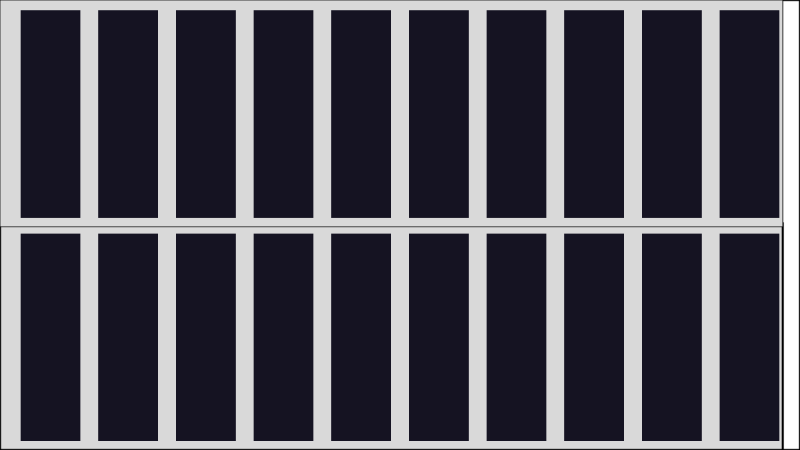 |
Models an individual photovoltaic module and its environment-adjusted I-V behavior. |
| MPPT charge controller | 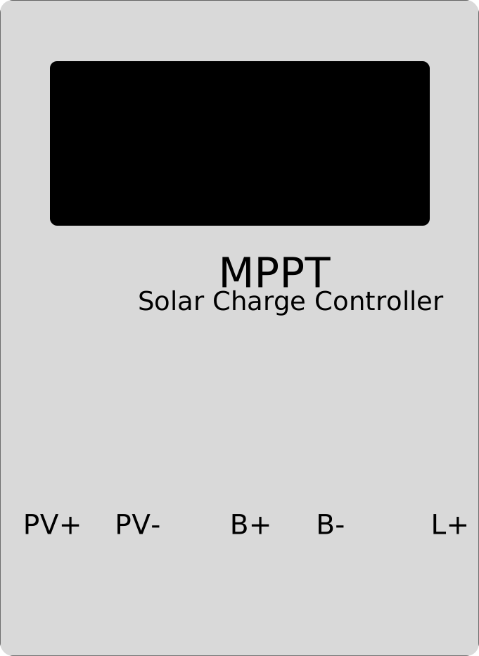 |
Tracks the available PV maximum-power point and converts power for a battery and DC load output. |
| PWM charge controller | 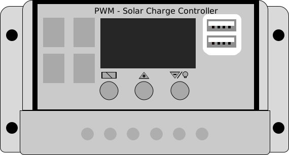 |
Pulls the array toward battery voltage and shows the characteristic difference between PWM and MPPT operation. |
| Battery |  |
Stores energy, supplies loads, accepts charge, and participates in series or parallel battery banks. |
| Battery inverter | 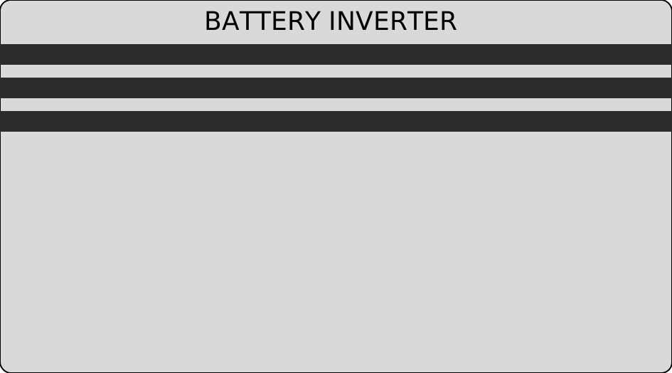 |
Converts battery DC into configurable 230 V, 50 or 60 Hz AC power for compatible appliances and fans. |
| Hybrid inverter | 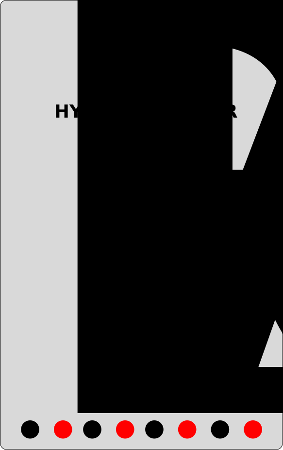 |
Combines an MPPT PV input, battery port, AC output, utility-grid port, and automatic grid-frequency synchronization. |
| Utility grid | 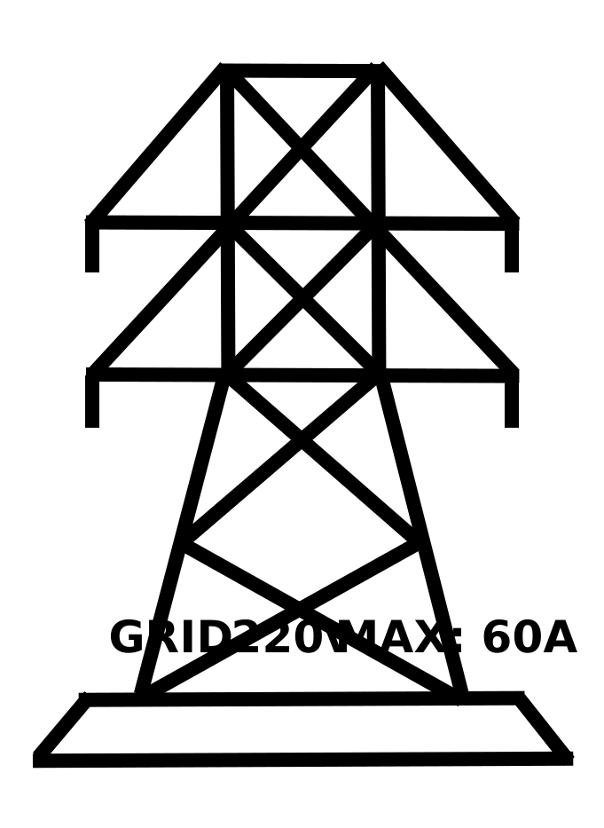 |
Provides configurable AC voltage and frequency and estimates grid import, export, energy, and cost. |
| Automatic transfer switch | 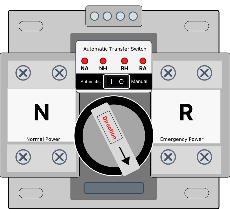 |
Transfers a common AC load between qualified normal and emergency sources using automatic or manual break-before-make operation. |
| Wall switch | 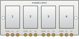 |
Models one to four independent two-way rockers with connectable COM, L1, and L2 canvas terminals. |
| Power breaker |  |
Opens or closes both conductors and latches an overcurrent trip. |
| Surge protective device | 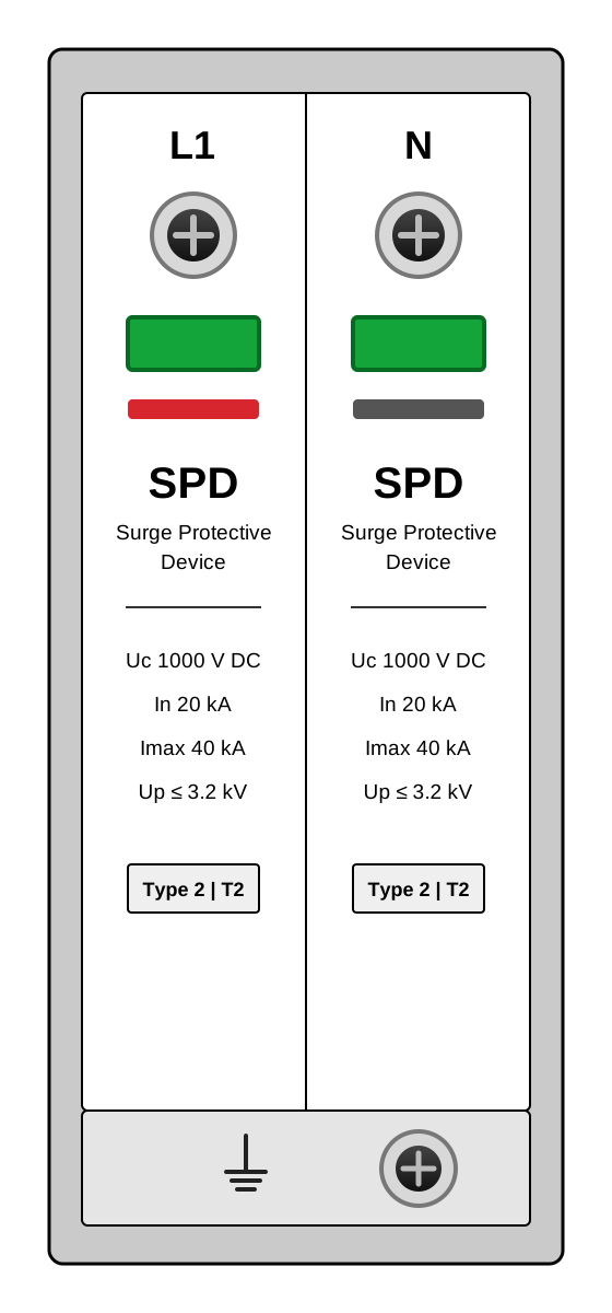 |
Tests L1 or neutral with an educational 8/20 microsecond surge impulse and models clamping, let-through voltage, cartridge wear, and diversion to earth. |
| Ground / Earth | 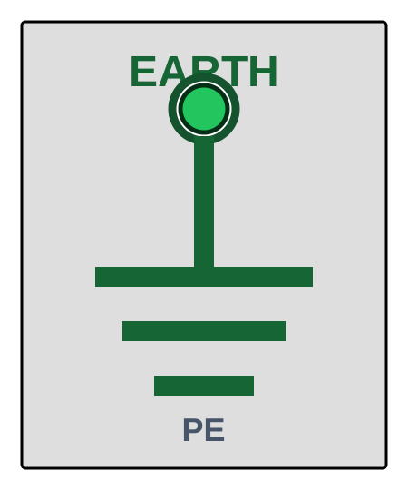 |
Provides the modeled protective-earth reference used by the SPD, with separate electrode resistance and surge bonding impedance. |
| MC4 fuse connector |  |
Protects one PV conductor with a compact gPV fuse and a latched blown state. |
| PV combiner box |  |
Parallels two through eight PV strings through independent gPV fuses and a main DC isolator. |
| Low-voltage disconnect | 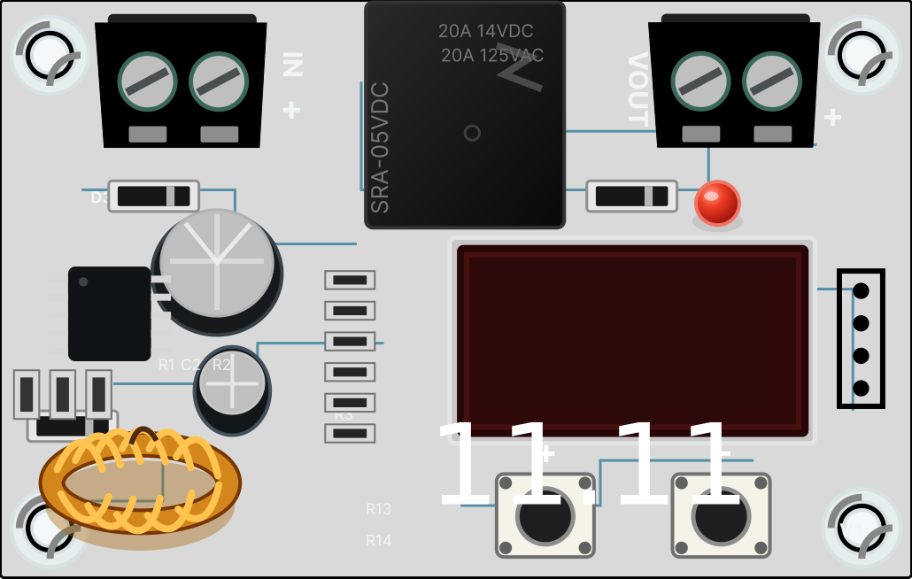 |
Disconnects DC loads at low battery voltage, applies recovery hysteresis, and latches open above its current or maximum input-voltage rating. |
| SPDT relay | 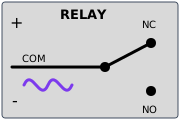 |
Switches COM from NC to NO when its configurable AC or DC coil reaches pickup voltage. |
| DC contactor | 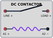 |
Uses an isolated DC coil to close a high-current normally-open positive contact while checking coil, contact-current, and switching-voltage ratings. |
| Extension socket |  |
Distributes one source to two through eight independently wired outlets. |
| Appliance |  |
Represents constant-power, resistive, constant-current, motor, or compressor loads with editable 50 Hz, 60 Hz, or 50/60 Hz ratings. |
| LED light bulb | 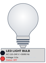 |
Models a 5 W AC electronic lamp across 110–240 V and 50/60 Hz, glowing yellow only while valid power is delivered. |
| Refrigerator | 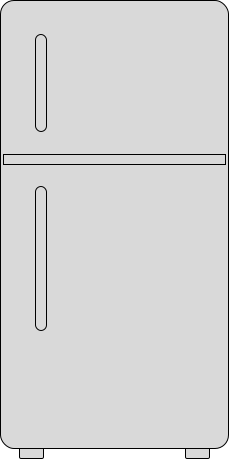 |
Models a thermostat-controlled AC compressor with startup surge, power factor, duty cycling, and accumulated energy. |
| Rice cooker | 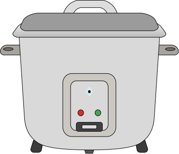 |
Models voltage-dependent resistive cooking power with live readings, runtime, and accumulated energy. |
| Washing machine | 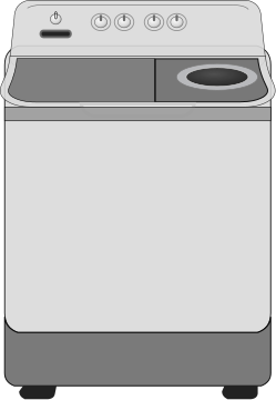 |
Models an AC motor load with power factor, startup demand, agitation duty cycling, and accumulated energy. |
| Television | 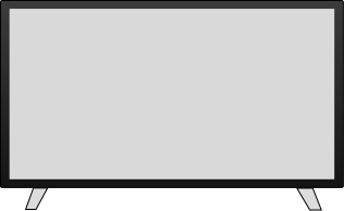 |
Models an AC constant-power electronic load with power factor and brief startup demand. |
| Electric kettle | 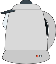 |
Models a high-power resistive heater whose watts and current respond to delivered voltage. |
| Laptop |  |
Models a laptop and wall adapter as a constant-power AC electronic load with power factor. |
| Fan |  |
Models a three-speed AC or DC motor load with power, RPM, startup behavior, frequency response, and V/Hz estimates. |
| Multimeter | 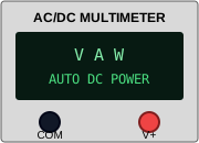 |
Measures voltage, current, real power, apparent power, power factor, and flow direction. |
| PV analyzer | 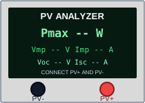 |
Tests an isolated panel or array for Voc, Isc, Vmp, Imp, Pmax, and a simulated I-V curve. |
A wire junction is also a node, although it does not use an equipment SVG. It appears as a compact branch point placed directly on a conductor.
Wall switch terminal wiring
The wall-switch node can be configured with one, two, three, or four independent gangs. Its width and height are independently adjustable, with the plate, rockers, labels, and terminal locations scaling together. Each gang behaves as a two-way SPDT mechanism: its rocker connects COM to either L1 or L2. Tap a rocker on the canvas or choose its contact position in the Inspector to change the energized path. For a typical one-way lamp circuit, route the AC live conductor to COM, connect L1 to the lamp live terminal, and connect neutral directly to the lamp neutral terminal.
Click any two different wall-switch terminals on the canvas to create a visible conductor and a real conductive link in the simulation. Supported combinations include L1-to-L1, L1-to-L2, COM-to-L1, and L2-to-COM within or across gangs. This supports multi-gang live-feed bridges and traveler arrangements, while warnings identify same-gang bridges that can bypass or defeat a rocker. The switch also compares simulated current and voltage with its editable contact ratings. It remains switching equipment—not overcurrent protection—so practical installations still require correctly sized conductors, breakers or fuses, enclosures, grounding, and code-compliant work by a qualified person.
Solar panel node: model a module or PV array
The solar panel node can use a built-in module preset or custom datasheet values. Editable specifications include rated maximum power (Pmax or Wp), Vmp, Imp, Voc, Isc, maximum system voltage, physical dimensions, weight, Pmax temperature coefficient, Voc temperature coefficient, and lowest design temperature.
For a new Custom panel, enter the manufacturer-listed Pmax / Wp, Vmp, and Imp directly; automatic calculation is off by default. PVAlign displays Vmp × Imp as a consistency check because datasheet values are often rounded. If you are experimenting without a complete datasheet, you can opt in to either Calculate Pmax automatically as Vmp × Imp or Calculate Imp automatically as Pmax ÷ Vmp. The modes are mutually exclusive to prevent a circular calculation.
Environmental inputs include cell temperature and shading. When the optional global Environment panel is enabled, a panel can instead use the simulated time, weather, irradiance, ambient temperature, and wind speed. PVAlign estimates cell temperature from those conditions and adjusts the panel's available voltage and current.
The panel model uses a piecewise I-V curve around short circuit, maximum power, and open circuit. PV array topology matters:
- Series modules add voltage and operate at a shared string current.
- Parallel strings add current and operate at a shared voltage.
- Series-parallel arrays combine those effects, subject to module mismatch and common operating-point constraints.
The array solver samples the combined curve and selects the highest calculated power point for an MPPT input. Each panel has a Bypass diode protection option: the recommended default models three protected substrings with one diode per substring, while None / not fitted represents a module without bypass protection. This lets the canvas show panel contribution, operating voltage, string current, output power, reverse-current conditions, and whether bypass behavior is active. A manufacturer datasheet should be used to confirm the actual construction; for example, a Canadian Solar module datasheet specifies an IP68 junction box with three bypass diodes, and Victron's panel documentation describes built-in bypass diodes that reduce shade-related power loss.
When panels with and without bypass diodes are placed in the same series path, PVAlign retains their individual configurations instead of assuming identical protection. A shaded protected substring is clamped near the bypass diode's forward voltage, reducing the panel's voltage while allowing string current to continue. A shaded substring without a diode can instead be driven into reverse bias, absorb electrical power, reduce array output, and develop a real-world hot spot. The affected panel receives a critical safety warning when that operating condition occurs; missing diode protection and mixed-protection series strings also receive advisory warnings because that arrangement is not recommended without explicit manufacturer approval.
Cold weather can increase PV open-circuit voltage. PVAlign therefore calculates a design Voc from the module's Voc temperature coefficient and minimum design temperature. That value is compared with the connected controller or hybrid inverter's absolute PV voltage limit—not only with the warm, operating voltage shown on the array.
For a practical introduction to array topology, read Series vs. Parallel Solar Panels and Understanding Solar Panel Specifications.
MPPT and PWM solar charge controller nodes
Both controller choices have PV, battery, and load terminal pairs, but they represent different electrical behavior.
MPPT charge controller
The MPPT node searches the connected array curve for its calculated maximum-power operating point. It then models DC-to-DC conversion between PV voltage and battery voltage. A high PV voltage can therefore become a lower battery-side voltage with more charging current, while remaining subject to conversion efficiency and current limits.
You can configure accepted battery chemistry, nominal system voltage, maximum PV input power, maximum PV voltage and current, maximum battery charge current, load-output current, efficiency range, standby consumption, battery-voltage limits, minimum state of charge, DC-load low-voltage disconnect and reconnect thresholds, and bulk, absorption, and float targets. The live inspector reports PV volts, amps, watts, design Voc, battery voltage and current, charge stage, controller state, conversion loss, standby loss, thermal behavior, current limiting, and active faults.
PWM charge controller
The PWM node connects the panel side much closer to battery voltage during charging. If an 18 V Vmp module charges a 12 V-class battery, the unused voltage does not automatically become proportionally higher output current. This is why the same panel and battery can show less harvested power through PWM than through MPPT.
The PWM model includes 12/24 V system behavior, an interactive display, front-panel controls, a switchable load output, battery profile settings, current limits, charge targets, standby power, night detection, and protection states.
Both models can optionally protect their dedicated DC load terminals with voltage hysteresis. The feature is disabled by default so controllers without load-terminal LVD support can be represented. When enabled, automatic defaults scale with the connected battery chemistry and nominal bank voltage, or the user can enter manual disconnect and reconnect voltages. At or below the disconnect voltage, only the load terminals switch off; solar charging can continue. The load remains latched off through the intermediate voltage range and reconnects only when battery voltage reaches the higher reconnect threshold.
For both controller models, an array that exceeds the configured maximum PV Voc triggers a PV-overvoltage condition and disables useful PV input. The simulator can also warn about reversed panels, terminal shorts, floating array sections, closed PV loops, mismatched parallel-string voltages, non-standard topologies, one array feeding multiple independent MPPT inputs, and a load improperly sharing an MPPT input bus.
Battery node and solar battery bank behavior
The battery node supports lead-acid, LiFePO4, and lithium-ion profiles. Its main inputs are nominal voltage, amp-hour capacity, state of charge (SOC), maximum charge percentage, maximum charge current, maximum discharge current, and a low-voltage BMS cutoff.
The inspector reports estimated terminal voltage, stored watt-hours, battery current, stored charging power, charging heat loss, temperature, charge stage, acceptance limit, discharge limit, and estimated time to the next charging or low-battery boundary. When simulated time moves forward, energy entering or leaving the bank updates battery state. Moving the clock backward changes environmental conditions without reversing battery history.
PVAlign also resolves connected batteries as a bank:
- A series bank adds voltage while every battery carries the same branch current. The first battery to reach a charge or discharge limit constrains the string.
- A parallel bank shares a common bus voltage, adds usable branch capacity, and divides external current among the connected batteries.
- Bank results include topology, voltage, amp-hours, watt-hours, branch behavior, equalization current, remaining energy, net stored power, and estimated charging time.
Battery-bank validation rejects mixed chemistries, closed series loops, unsafe nominal-voltage mismatch, large open-circuit-voltage differences, and severe SOC mismatch. Smaller SOC differences can remain operational with a caution because closely matched terminal voltage does not guarantee closely matched stored energy—especially with LiFePO4's relatively flat voltage curve.
The battery model is useful for exploring relationships among volts, amp-hours, watt-hours, current limits, and SOC. It is not a manufacturer-specific BMS or electrochemical aging model. See Battery Storage Guide and Battery Capacity: Ah vs. Wh vs. kWh for supporting concepts.
Battery inverter node
The battery inverter has a DC input terminal pair and an AC output pair. It models continuous wattage, startup surge capacity and duration, nominal battery voltage, conversion efficiency, AC output voltage and frequency, standby consumption, maximum DC input current, minimum DC voltage, maximum DC voltage, and minimum battery SOC. New inverter nodes default to 230 V AC and 60 Hz, while the output can be changed to 50 Hz for equipment designed for that frequency.
When an AC load is connected, PVAlign works backward from the required AC real and apparent power to estimate DC input power and current. The inspector shows input current, input power, output watts and VA, battery DC range, maximum DC input current, standby and total losses, and any active protection reason.
This makes an important sizing relationship visible: a moderate AC load on a low-voltage battery bank may require a large DC current. That current also flows through the battery conductors, where resistance and voltage drop matter.
Hybrid inverter node
The hybrid inverter is the most integrated conversion node. It has four terminal pairs:
- PV input
- Battery connection
- AC load output
- Utility-grid connection
Its settings cover inverter wattage, surge rating and duration, battery voltage and chemistry, AC output voltage, AC frequency mode, grid-frequency tolerance, conversion efficiency, standby power, battery charge and discharge limits, battery-voltage window, back-to-grid SOC, back-to-battery SOC, minimum SOC, MPPT operating range, MPPT startup voltage, PV input current, and absolute PV Voc limit. Presets are available for several representative MPPT voltage ranges, but custom limits can be entered from a product datasheet.
SOC source-transfer control is optional and disabled by default because not every hybrid inverter supports separate thresholds. When enabled, its recommended starting thresholds are 20% back to grid and 50% back to battery. Once battery SOC reaches 20%, the hybrid inverter stops using the battery for load support and latches into grid supply when the grid is available. Solar can continue charging the battery, but battery discharge remains blocked at 21% or any other intermediate value. The battery becomes eligible to support loads again only when SOC reaches 50%. This hysteresis prevents repeated source changes around one low-SOC threshold. When the feature is disabled, only the minimum-SOC cutoff applies, without a separate recovery threshold. Grid charging is not currently modeled.
The AC Frequency Mode has three choices: Auto (Grid), 50 Hz, and 60 Hz. Auto is the default. When an acceptable grid is connected, Auto follows the grid's live voltage and frequency before allowing import or export. A 60 Hz grid therefore produces approximately 60 Hz at the grid-connected AC output, while a 50 Hz grid produces approximately 50 Hz. If the grid is unavailable or rejected, backup output returns to the stored off-grid frequency, which defaults to 60 Hz.
Selecting fixed 50 Hz or 60 Hz makes that the inverter's islanded output target. A wired grid outside the configured frequency tolerance is rejected, so it contributes no import or export power. The inverter may continue supplying its AC output from PV or battery in islanded mode when energy is available. PVAlign models this frequency decision and voltage synchronization as a steady-state operating rule; it does not simulate the waveform, phase-locking transient, anti-islanding test sequence, or a product-specific grid-code profile.
The simulation balances PV production, connected AC demand, battery charge or discharge, conversion loss, standby demand, and accepted grid power. Its live state reports PV voltage/current/power, MPPT state, battery current and SOC, synchronized AC output, apparent power, excess solar, load state, protection state, grid frequency state, and a plain-language flow status.
Utility grid node and energy-cost estimate
The utility grid node is an AC source for a hybrid inverter or directly connected compatible AC loads. Its configurable values include voltage, frequency, maximum current, billing currency, and energy price per kilowatt-hour. New grid nodes use Philippine-oriented defaults of 230 V AC and 60 Hz, but 50 Hz can be selected for other regional scenarios.
PVAlign reports import demand, current, accumulated imported energy, estimated cost per hour, accumulated import cost, export power, export current, and connection status. Imported energy advances with simulated time, so the result can be used to compare operating scenarios rather than only instantaneous watts.
The cost estimate is deliberately simple. It does not model demand charges, time-of-use schedules, tiered pricing, fixed charges, taxes, export compensation rules, or utility interconnection requirements.
Automatic transfer switch (ATS) node
The automatic transfer switch connects one common AC load bus to either a Normal source or an Emergency source. Supported source pairs include the utility grid, a battery inverter AC output, and a hybrid inverter AC output. Each source must provide a complete live-and-neutral pair; PVAlign does not accept half of one source pair or treat an arbitrary load terminal as an ATS supply.
The hardware-style ATS has eight connection points arranged around the screw locations shown in its SVG:
- Top-left Normal input: Normal N and Normal L
- Top-right Emergency input: Emergency N and Emergency L
- Bottom-left N OUT: the neutral and live output below the Normal side
- Bottom-right R OUT: the neutral and live output below the Emergency side
The four lower terminals form two switched output pairs in the illustrated mechanism. To supply one load circuit, join N OUT L and R OUT L onto the same downstream live conductor, then join both lower neutral terminals onto the same downstream neutral conductor. Connect the load or an AC extension socket to that common bus. Never join live to neutral, and never join the two source inputs together. When Normal is selected, only the Normal input is internally connected to its lower output pair. When Emergency is selected, only the Emergency input is connected to its lower output pair. The unselected internal path remains open.
Before a source is eligible, the ATS checks that it is connected, powered, within the configured voltage window, and within the configured frequency window. New nodes default to 230 V AC, 60 Hz, a ±10% voltage window, and a ±2 Hz frequency window. The inspector reports each source as available, disconnected, off, outside the voltage range, or outside the frequency range. This lets a wired but unsuitable backup source remain visibly rejected instead of being treated as usable power.
Automatic mode uses Normal as the preferred source by default, although Emergency can be selected as preferred. A healthy preferred source closes immediately during initial energization. If the active source fails qualification, the ATS opens the load first. It then waits for the alternate-source transfer delay and the open-transition interval before closing the alternate source. When the preferred source returns, the ATS remains on the alternate source for the return delay, opens the active path, observes the open-transition interval, and then reconnects the preferred source. The defaults are a 1 second transfer delay, 1 second return delay, and 0.1 second open transition.
The operating selector also provides Manual – Normal, Manual – Emergency, and Manual – Off. A manually requested source still must pass the voltage and frequency checks; manual selection does not make an unacceptable source safe. Manual Off leaves both internal source paths open.
The ATS state reports the selected and pending sources, output voltage and frequency, load current, transfer countdown, maximum-voltage warning, and contact overload. Its default contact rating is 63 A, maximum source voltage is 400 V AC, and modeled closed-contact resistance is 3 mΩ. The inspector warns when the two lower output pairs have not been joined into a complete downstream load bus or when calculated current exceeds the contact rating.
Reproduce an ATS transfer in PVAlign
- Add one utility-grid node, one battery inverter or hybrid inverter, one ATS, and one compatible AC load or extension socket.
- Connect the utility live and neutral pair to the upper Normal terminals. Connect the backup source AC pair to the upper Emergency terminals.
- Join both lower live outputs at one wire junction and both lower neutral outputs at a separate wire junction. Connect the load across those two junctions.
- Leave the ATS in Automatic mode with Normal preferred. Confirm that the load reports the Normal source.
- Switch the grid off or move its voltage outside the ATS tolerance. The load should disconnect during the countdown and then resume from Emergency.
- Restore the grid and advance simulated time. The ATS should hold Emergency through the return delay before performing another open transition back to Normal.
- Change the backup source to 50 Hz while the ATS expects 60 Hz with a ±2 Hz window. The Emergency source should be rejected as FREQUENCY OUT OF RANGE.
PVAlign models an educational, two-pole, single-phase open-transition sequence. It does not reproduce contact bounce, arcing, waveform phase, generator cranking and warm-up controls, three-phase sensing, neutral-grounding rules, bypass isolation, short-circuit withstand ratings, or a manufacturer's controller logic. Real transfer equipment must be selected and wired from its current installation manual and applicable electrical rules. For hardware context, Schneider Electric describes open transition as breaking the active source before transfer, while Eaton's ATS fundamentals distinguishes manual and automatic transfer operation.
Power breaker node
The power breaker is a configurable two-pole AC or DC protective node. It defaults to a 50 × 90 px hardware-style view with all four canvas terminals aligned to the illustrated terminal screws. Its linked blue handle moves between the visible ON and OFF positions when it is switched, forced open by a type mismatch, or tripped by protection. It can be assigned a current rating, resized visually, and configured for terminal orientation. When closed, it carries both conductors through the device. When measured current exceeds the rating, it trips, opens the circuit, and remains latched until reset.
| Breaker category | Current | Typical modeled application |
|---|---|---|
| DC MCB | DC | PV strings, charge controllers, and small DC circuits |
| DC MCCB | DC | Battery banks, large inverter DC inputs, and high-current DC feeders |
| AC MCB | AC | Inverter AC outputs and household branch circuits |
| AC MCCB | AC | Main AC feeders and higher-current systems |
| AC RCBO | AC | AC load overcurrent and residual-current protection |
MCB selections use a lower current range and fixed representative starting values, while MCCB selections support the simulator's higher-current range and begin with slower, adjustable protection settings. The AC RCBO compares the modeled line and neutral pole currents and trips when their residual imbalance reaches its configurable IΔn threshold. Its inspector also provides an injected-current test for demonstrating the latched residual-current trip. These category defaults are examples, not universal product ratings.
For hardware context, Schneider Electric's MCB and MCCB guidance describes MCBs as lower-current devices with factory-set trip characteristics and MCCBs as higher-capacity devices that commonly provide adjustable protection settings. ABB's RCBO documentation describes combined overload, short-circuit, and earth-fault-current protection plus a test pushbutton. The simulator follows those functional distinctions at an educational steady-state level; it does not certify device selection, breaking capacity, selectivity, or code compliance.
An AC breaker placed in a detected DC path—or a DC breaker placed in an AC path—enters a type-mismatch state rather than pretending to be valid protection. The node is valuable for showing how an opened or tripped protective device changes every downstream operating state.
The trip model is an educational current threshold, not a manufacturer trip curve. Real breakers depend on device type, interrupting rating, time-current behavior, ambient conditions, enclosure, polarity requirements, voltage rating, and applicable code.
Surge protective device and Ground / Earth nodes
The Type 2 surge protective device (SPD) is a shunt-protection node with two upper conductor terminals, L1 and N, and one lower protective-earth (PE) terminal. It can represent an AC line-to-earth and neutral-to-earth arrangement or a two-conductor DC/PV arrangement. The SPD is connected in parallel with the protected circuit: connect L1 and N to the appropriate conductors, then connect PE to a Ground / Earth node. It is not placed in series like a breaker and does not carry the normal load current through an input and output pair.
The Ground / Earth node provides the modeled earth reference. Its inspector separates earth-electrode resistance, used as the low-frequency grounding value, from surge bonding impedance, used for the fast impulse calculation. This distinction matters because the voltage developed during a surge depends on both current and the high-frequency impedance of the bonding path. The default model uses 5 ohms of electrode resistance and 0.02 ohms of surge impedance, and both values are editable.
The SPD inspector supports DC/PV or AC labeling and configurable maximum continuous operating voltage (Uc), nominal discharge current (In), maximum discharge current (Imax), voltage protection level (Up), and energy endurance. Its built-in educational surge generator applies an 8/20 microsecond current impulse to either L1 or N. A test requires the selected upper terminal to be connected, the PE terminal to be wired, and that PE path to reach a Ground / Earth node.
After a test, the inspector reports the outcome, tested pole, let-through voltage, diverted current, absorbed energy, ground rise, earth-path status, remaining cartridge health, and coordinated backup-breaker result. A surge at or below Uc does not clamp. A pulse above Imax fails the selected cartridge, while repeated energy absorption reduces its modeled health until replacement is required. Replacing the cartridges resets the simulated failed state; it does not change the external wiring.
A correctly coordinated backup breaker does not trip merely because the SPD diverted a normal lightning impulse. Its job is to disconnect the SPD if the protective element subsequently fails short circuit and power-frequency follow current flows. PVAlign therefore keeps a connected, current-type-compatible AC MCB, AC MCCB, DC MCB, or DC MCCB closed after a protected test. If the SPD exceeds Imax, reaches its modeled energy end of life, or the user selects Force short-circuit failure, that breaker trips and latches open. The model treats those SPD failure outcomes as a short-circuit failure for this educational coordination test.
For a typical low-current AC Type 2 SPD branch, the backup device is usually a manufacturer-specified AC MCB; higher-current feeders may use an AC MCCB, while PV systems require a suitably DC-rated MCB or MCCB. PVAlign does not select an AC RCBO as the primary SPD backup disconnector. Schneider Electric's SPD coordination guide explains that the disconnecting circuit breaker should not trip on the surge current but must protect against SPD short-circuit degradation. ABB's surge-protection guidance likewise describes backup protection by an MCB or fuse and recommends selective residual-current devices where nuisance tripping must be avoided. Always follow the selected SPD manufacturer's required backup device and coordination tables.
For a basic test, place a matching AC or DC MCB/MCCB upstream, branch the SPD's L1 and N terminals onto its protected conductors, connect PE directly to the Ground / Earth node, choose the test conductor, enter the impulse voltage and peak current, and select Trigger surge test. Post-surge SPD condition defaults to Force short-circuit failure so a new SPD immediately demonstrates a latched backup-breaker trip. Select Automatic from Imax and endurance when you want a normal coordinated pulse to ride through and failure to occur only after Imax is exceeded or modeled endurance is exhausted. Explicit saved selections remain unchanged. Short, direct bonding paths are important in real installations; the canvas drawing length is not currently converted into high-frequency lead inductance, so the editable surge impedance represents that effect only as a planning approximation.
The surge generator is an educational calculation, not a laboratory impulse test or proof of compliance. Real SPD selection and installation depend on the supply topology, nominal voltage, temporary overvoltage exposure, SPD type, short-circuit and backup-protection coordination, conductor routing and inductance, equipotential bonding, earthing system, prospective fault current, manufacturer instructions, and applicable electrical rules. A ground symbol on a diagram does not by itself establish a safe grounding or neutral-to-earth bonding arrangement.
Low-voltage disconnect module for battery protection
The low-voltage disconnect, or LVD, is a two-pole DC protection node placed between a battery source and a DC load or inverter input. Its input and output pairs preserve polarity. When the relay is closed, downstream equipment receives the battery voltage; when protection opens the relay, the output becomes 0 V and downstream current stops.
Automatic threshold mode detects the connected battery bank's nominal voltage and chemistry. It scales a chemistry-specific 12 V-class protection profile to the complete bank. For example, a 24 V lead-acid system uses an estimated 22.0 V disconnect threshold and 25.0 V reconnect threshold instead of incorrectly applying the 11.0 V and 12.5 V values intended for a 12 V system. LiFePO4 and lithium-ion batteries use different base profiles before voltage scaling.
The separate reconnect voltage provides hysteresis. Once input voltage reaches the disconnect threshold, the LVD remains latched off while voltage is between the disconnect and reconnect values. It closes again only after the source recovers to the higher threshold. This avoids treating a small unloaded-voltage rebound as a stable recovery.
Manual mode is available for comparing datasheet settings. If those values are substantially inconsistent with the detected battery system, the inspector displays the detected nominal voltage and recommended thresholds. This makes a 12 V-oriented setting on a 24 V bank visible instead of silently accepting it.
The module current rating is also active in the simulation. If measured DC current exceeds the configured rating (20 A by default), the LVD enters a latched overcurrent fault, opens its output, records the trip current, and requires a reset. Resetting while the oversized load remains connected causes another fault. A correctly rated DC breaker or fuse is still required in a real installation because an LVD relay's current marking does not establish conductor protection or an adequate interrupting rating.
The maximum input-voltage rating is configurable from 1 V to 1,000 V and defaults to 60 V. Input above that rating creates a latched OVERVOLTAGE RATING EXCEEDED state, records the trip voltage, and opens the simulated output. This is an educational damage-limit response, not a claim that a real LVD contains safe overvoltage protection. Real modules may fail when their maximum rating is exceeded, so the manufacturer datasheet remains authoritative.
The canvas module defaults to 180 x 106 px and can be resized independently in width and height. Its terminals and attached conductors move with the selected dimensions, so resizing changes the drawing without changing the electrical configuration.
MC4 inline PV fuse connector
The MC4 fuse connector is a compact single-conductor protection node placed between one solar-panel lead and the matching PV input of an MPPT or PWM charge controller or hybrid inverter. Its dedicated panel and PV-input terminals reject batteries, AC circuits, loads, and non-PV controller terminals. The inspector can protect either the positive or negative PV conductor.
The default model is a 15 A, 1,000 VDC gPV fuse holder with 5 mΩ closed resistance. PVAlign measures the string current and applies a simplified time-current curve: normal current passes continuously, sustained overcurrent accumulates toward melting, and very high fault current opens the fuse quickly. Once blown, the circuit remains open until the fault is removed and Replace fuse is selected.
The voltage rating is compared with the connected array's cold-design open-circuit voltage. Exceeding that rating produces a warning rather than pretending the fuse can safely interrupt beyond its specified voltage. Real fuse selection must also respect the module's maximum series-fuse rating, array short-circuit current, cable ampacity, ambient derating, required breaking capacity, applicable electrical code, and the exact manufacturer's time-current curve.
PV combiner box for parallel strings
The PV combiner box accepts two through eight complete solar strings and joins them onto one positive and negative PV output for an MPPT charge controller or hybrid inverter. Each input remains a distinct branch in the circuit solver, so parallel string currents add at the output instead of being treated as one oversized panel lead. A string input accepts only matching solar-panel terminals; the output accepts only matching controller or hybrid-inverter PV terminals.
The default enclosure uses 15 A gPV string fuses, a 1,000 VDC system-voltage rating, a 125 A output bus and isolator, and protection on both ungrounded conductors. String fuse ratings are configurable from 1 A to 32 A, while the combined output rating is configured separately up to 250 A. This separation matters: a 15 A or 20 A string fuse protects one branch, but the combiner bus and output conductors must carry the sum of the active branch currents.
Each string has an independent time-current accumulator and latched open state. Opening the main DC isolator disconnects both output poles without replacing any fuse. The inspector reports every branch current, total output current, cold-design voltage, open fuses, output overload, and enclosure voltage-rating warnings. The model covers steady-state combining and overcurrent behavior; it does not simulate lightning impulses or certify surge-protective devices, interrupting capacity, enclosure suitability, or code compliance.
SPDT relay node and control wiring
The single-pole double-throw relay has five terminals: coil positive, coil negative, common (COM), normally closed (NC), and normally open (NO). The coil circuit is electrically isolated from the contact circuit. Applying coil voltage does not feed COM automatically; COM must be connected to the source being switched.
With the coil off, COM connects to NC. When coil voltage reaches the configured pickup percentage, the moving contact transfers COM to NO. Once energized, the relay remains picked up until voltage falls below the lower dropout threshold, reproducing relay hysteresis instead of rapidly switching at one exact voltage.
The inspector supports AC or DC coil selection, rated coil voltage, coil resistance, pickup and dropout percentages, and contact-current rating. PVAlign calculates coil current and power, warns when coil voltage exceeds 110% of its rating, rejects a detected AC/DC coil mismatch, and warns when switched current exceeds the contact rating.
For a normally-off DC fan controlled by an LVD, connect LVD output positive to both the relay coil positive and COM through a wire junction, connect LVD output negative to coil negative and fan negative, and connect NO to fan positive. This arrangement is valid but functionally redundant when the LVD powers both the coil and contact source; a relay is more useful when its coil is driven by a separate control circuit.
DC contactor node for high-current switching
The DC contactor has an isolated DC coil at A1+ and A2− and one normally-open main positive contact from LINE+ to LOAD+. Energizing the coil does not supply the main contact: LINE+ must receive the source positive conductor, LOAD+ feeds the load positive terminal, and the load negative conductor returns separately to the source negative through a wire junction when branching is required.
PVAlign models coil resistance and consumption, pickup and dropout hysteresis, closed-contact resistance, maximum switching voltage, and main-contact current rating. It warns about coil overvoltage, excessive switched voltage, and contact overload. These limits are educational; a real installation still requires a correctly rated DC contactor, fuse or breaker, conductors, suppression, enclosure, and manufacturer-approved wiring.
The node defaults to 130 x 90 px and can be resized independently in width and height. Its terminals and attached wires scale with the drawing without changing the circuit topology.
Extension socket node and branch distribution
The extension socket distributes one incoming AC or DC supply to between two and eight outlet pairs. Each load must use the positive and negative terminals of the same numbered outlet. The inspector shows circuit type, current rating, used outlets, total current, total load, and whether the strip is disconnected, active, overloaded, or connected to an incompatible circuit.
This node is convenient for building parallel load branches without stacking every branch directly onto one source terminal. It also demonstrates that a distribution device does not create energy: the source and upstream conductors must still carry the combined demand of all active outlets.
Appliance node
The configurable appliance node represents AC or DC loads. Built-in starting points include an LED light, television/electronics load, heater or kettle, and pump or motor. You can also define a custom load. Dedicated LED light bulb, refrigerator, rice cooker, washing machine, television, electric kettle, and laptop nodes provide recognizable equipment illustrations and appliance-specific starting values without crowding the generic controls.
The dedicated LED Light Bulb starts as a 5 W AC constant-power electronic load with a 110–240 V operating window, 50/60 Hz compatibility, and an editable power factor. Its bulb remains gray while disconnected, switched off, under-voltage, over-voltage, frequency-incompatible, or otherwise unpowered. It changes to yellow with a soft glow only when the circuit solver delivers valid operating power. The calculated current, apparent power, energy, voltage state, and upstream inverter or breaker loading use the same appliance model as other electronic loads.
Available load behaviors include constant power, resistive, constant current, and motor/compressor. Important settings include rated voltage, running watts or current, power factor for AC loads, startup multiplier, startup duration, acceptable voltage range, AC frequency rating, acceptable frequency range, duty-cycle percentage, and cycle length. An AC load can be marked 50 Hz, 60 Hz, or 50/60 Hz. A dual-rated load accepts either standard frequency without mismatch stress.
The live result shows whether the appliance is running, disconnected, in a duty-cycle off period, starting, undervoltage, overvoltage, outside its frequency rating, overloaded, or connected to the wrong supply type. It also reports delivered watts, VA, current, actual voltage and frequency, accumulated energy, runtime, frequency-stress time, equivalent operating age, relative life rate, and associated wire loss. Equivalent age and relative life are educational stress indicators, not manufacturer warranty predictions.
What happens when a 50 Hz appliance receives 60 Hz?
PVAlign does not switch every 50 Hz appliance off when connected to 60 Hz. The response depends on the selected load behavior and frequency range:
- A 50/60 Hz-rated load operates normally on either standard frequency.
- A resistive heater, kettle, or incandescent-type load keeps its voltage-dependent electrical behavior. If its entered nameplate range excludes the source frequency, PVAlign flags that fact but does not invent a large frequency-aging penalty.
- A constant-power or constant-current electronic load outside its entered frequency range receives a warning and an estimated stress factor.
- A motor, fan, pump, or compressor outside its range receives a motor-frequency warning. The simulator changes the frequency-dependent speed estimate and calculates V/Hz, approximate torque capability, stress time, and equivalent age.
- A device with Stop Outside Frequency Range enabled refuses to run when the source is outside its entered range.
For an AC motor, synchronous speed is estimated from:
Synchronous RPM = 120 × frequency ÷ motor poles
A four-pole motor therefore has a synchronous speed of 1,500 RPM at 50 Hz and 1,800 RPM at 60 Hz. Actual induction-motor shaft speed is lower because of slip. Motor poles are internal magnetic poles, not the external wire terminals.
PVAlign also compares the operating V/Hz ratio with the rated V/Hz ratio. A 230 V, 50 Hz motor has a rated ratio of 4.6 V/Hz. Supplying the same motor with 230 V at 60 Hz gives about 3.83 V/Hz. The simulator uses that ratio to estimate available torque capability, while recognizing that real results also depend on motor design, slip, mechanical load, cooling, and manufacturer limits. The equipment nameplate remains the deciding specification.
Refrigerator compressor load node
The refrigerator is a dedicated AC appliance that uses the shared load-calculation engine while exposing only refrigerator-relevant controls. Its default electrical ratings are 230 V, 60 Hz, 150 W, and 0.8 power factor. Because AC current depends on apparent power, the running current is calculated from watts divided by voltage and power factor rather than watts divided by voltage alone.
The default compressor startup demand is three times the running apparent power for two seconds. After startup, thermostat behavior uses a 35% duty cycle over a 30-minute cycle by default. This means the compressor alternates between running and duty-cycle-off states instead of drawing its rated power continuously. Users can edit the ratings, voltage window, startup multiplier and duration, duty cycle, and cycle length in the inspector.
The refrigerator reports rated values, delivered voltage, real power, current, operating state, and whether both supply conductors are connected. Its current also contributes correctly to upstream extension-socket, inverter, battery, conductor, and protection calculations. For example, a 150 W refrigerator at 220 V and 0.8 power factor draws approximately 0.85 A while running before wire losses.
The canvas node defaults to 180 px wide and 350 px high. Width and height can be adjusted independently from 60 to 240 px and 120 to 480 px. The positive and negative terminals scale with the cabinet, and connected wire endpoints remain attached after resizing.
Dedicated household appliance load nodes
The other five dedicated household nodes use the same topology-aware load engine as the refrigerator, but each starts with an electrical behavior appropriate to the illustrated equipment. Their ratings remain editable because actual nameplates vary by model, region, operating mode, and efficiency.
| Dedicated load | Default electrical model | Behavior represented |
|---|---|---|
| Rice cooker | 230 V, 700 W, power factor 1.0, resistive | Heating-element resistance is derived from the rated voltage and watts. At 220 V, the calculated heating power is about 641 W rather than remaining at 700 W. |
| Washing machine | 230 V, 500 W, power factor 0.8, motor | A 2.5-times startup demand lasts two seconds by default, followed by a 70% agitation duty cycle over ten minutes. |
| Television | 230 V, 100 W, power factor 0.9, constant power | The electronic supply requests approximately the configured real power across its valid voltage range while apparent power and conductor current include power factor. |
| Electric kettle | 230 V, 1,500 W, power factor 1.0, resistive | Delivered heating power follows the square of voltage. A 1,500 W kettle rated at 230 V draws about 1,372 W and 6.24 A at 220 V. |
| Laptop | 230 V, 65 W, power factor 0.9, constant power | Represents the laptop together with its wall adapter, including a brief 1.1-times startup demand and approximately 0.33 A running current at 220 V. |
These dedicated nodes are fixed AC loads. Their supply selector is locked, and PVAlign rejects a direct connection to a DC battery, solar-panel output, or incompatible controller output. The refrigerator, washer, TV, kettle, rice cooker, and laptop must instead receive compatible AC from a battery inverter, hybrid inverter, utility grid, or AC extension socket. A real laptop can run from a suitable regulated DC or USB-C power-delivery converter, but that converter is separate equipment; an unregulated battery connection is not treated as equivalent to the laptop's charger.
Each dedicated appliance reports delivered voltage, real power, apparent power, current, status, runtime, accumulated energy, and associated conductor loss in its inspector. Its current is included upstream in extension-socket, inverter, battery, wire, and protection calculations. The SVG on the canvas also shows live voltage, power, and operating state. Width, height, and terminal positions can be adjusted without changing the electrical model.
Fan node
The fan node is a specialized motor load with editable DC and AC presets. It supports three speed levels, with separate watts and RPM for each level, plus power factor, startup multiplier, startup duration, start voltage, run voltage, maximum operating voltage, duty cycle, and on/off control.
This makes direct-PV experiments possible for a compatible single panel and DC fan, while also supporting battery, inverter, controller-load, extension-socket, and grid-fed scenarios. AC fans can be rated for 50 Hz, 60 Hz, or 50/60 Hz. The motor-pole setting supports synchronous-speed calculation, while the live state shows actual RPM, V/Hz, approximate torque capability, frequency stress, stalled, starting, running, duty-cycle-off, under-voltage, and over-voltage behavior.
Multimeter and power analyzer node
The multimeter is a passive measurement node connected across a supported source, bank, inverter port, controller port, or load. Depending on the circuit, it reports DC or AC RMS voltage, current, watts, apparent power, power factor, frequency, power-flow direction, source count, topology, and solver status.
Its configurable limits include maximum DC voltage, DC current, AC RMS voltage, and AC current. The meter reports an overload status when the simulated measurement exceeds those limits. For battery banks it can also show combined capacity, energy, and SOC; for PV it can show the available maximum-power values.
PV analyzer and I-V curve tracer node
The PV analyzer is designed specifically for an isolated solar panel or reducible series, parallel, or series-parallel PV array. A simulated test performs:
- An open-circuit measurement for Voc
- A short-circuit measurement for Isc
- A maximum-power search for Vmp, Imp, and Pmax
- A 41-point voltage sweep from 0 V through Voc for the displayed I-V curve
The analyzer uses the same environment-adjusted panel and conductor model as the operating-point solver. It shows panel count, topology, average irradiance, average cell temperature, and its configured voltage/current limits.
Testing is blocked for reversed leads, insufficient irradiance, unsupported topology, external equipment attached to the array, or array Voc/Isc above the analyzer rating. A passive multimeter may remain connected. During a valid test, the canvas holds the panels at the measured maximum-power test point for comparison; this is simulated test power absorbed by the analyzer, not continuous energy delivered to another load.
Wires, conductor sizing, and junction nodes
Every visible wire is part of the model. New-wire defaults can be set for length, cross-sectional area, and copper or aluminum conductor material. Individual wires can then be edited for:
- Cable type: PV, battery, general DC, or AC
- Cross-sectional area in mm² and approximate AWG equivalent
- One-way length
- Copper or aluminum conductor material
- Free-air, conduit, bundled, or direct-buried installation
- Local or global ambient temperature
- Conductor temperature rating
PVAlign estimates resistance, current, voltage drop, I²R power loss, thermal ampacity, conductor temperature, thermal loading, and a minimum suggested wire size. Branch conductors display branch current, while a shared trunk can display combined downstream current.
Wire color and glow provide additional feedback for polarity, power type, and heat. These results are useful for demonstrating why low-voltage battery circuits often require large conductors, but they are not a final code-compliant ampacity calculation. The current model does not fully account for every terminal rating, bundling arrangement, enclosure, continuous-load factor, correction rule, or local code edition.
Environment and time-based simulation
The optional Environment panel links the whole circuit to a shared scenario. Available clear-sky, partly cloudy, cloudy, rain, and manual modes control irradiance, ambient temperature, and wind; a time-of-day curve changes preset irradiance between sunrise and sunset.
These inputs affect panels that opt into the global environment and wires that use the environment temperature. Advancing time also accumulates battery energy changes, appliance and fan runtime, load energy, frequency-stress time, equivalent operating age, and grid-import energy and cost. This is a sequence of steady-state estimates across selected time steps, not a high-frequency transient or full annual-yield simulation.
Canvas, presets, saving, and sharing a circuit
PVAlign includes editor features that make larger systems easier to build and revisit:
- Drag-to-place parts and terminal-to-terminal wiring
- Pan, mouse-wheel zoom, touch pan, and pinch zoom
- Optional alignment grid and interactive minimap
- Undo, redo, copy, paste, and deletion shortcuts
- A resizable inspector for component and conductor settings
- Live wire-current, loss, and temperature overlays
- Saved 0–100% ground-wire opacity control, defaulting to 50%, for green protective-earth conductors
- Built-in reference circuits for grid-tied, off-grid, PWM, 3S3P, series, parallel, battery, inverter, and direct-solar-fan examples
- Browser-local saving
- JSON import and export
- PNG circuit export for printing or documentation
- A browser-local solar project budget planner for equipment prices, purchase priorities, planned dates, receipt-style PDF printing, and PNG export
Loading a preset or importing a circuit replaces the current canvas, so export work you want to preserve first. Browser-local saving remains on that browser and device unless the circuit is also exported as JSON.
A detailed first circuit in PVAlign
- Open the PVAlign Solar Simulator.
- Load a reference preset or place one solar panel, one correctly rated charge controller, and one battery.
- Open each node's inspector and enter values from the relevant equipment datasheet.
- Connect matching positive and negative terminal pairs.
- Inspect PV voltage/current/power, controller loss, battery current, and charge stage.
- Add a compatible load and observe how charging power changes after load demand and conversion losses are included.
- Edit conductor length and size to compare voltage drop, loss, and temperature.
- Try a second panel in series, then in parallel, while watching array voltage, current, design Voc, and controller limits.
- Enable the Environment panel and move time forward to compare weather conditions and battery progression.
- Export the circuit before loading another preset or making a major topology change.
What PVAlign calculates—and what it does not
PVAlign provides physics-informed steady-state estimates for education and preliminary planning. Displayed decimals improve readability; they do not claim laboratory accuracy. The simulator can reveal relationships and obvious incompatibilities, but it cannot reproduce every manufacturer algorithm, protection curve, transient, thermal condition, shading pattern, installation detail, aging effect, utility rule, or electrical-code requirement.
Do not use a simulated result as the sole basis for purchasing, construction, permitting, grid connection, or safety approval. Verify every safety-critical rating against current manufacturer documentation, use the electrical rules that apply at the installation location, and have a qualified professional review real systems where required.
Frequently asked questions
Is PVAlign free to use?
Yes. PVAlign currently provides free access to its solar learning articles and interactive solar panel simulator.
Does PVAlign replace professional solar design software?
No. PVAlign is intended for education, comparison, and preliminary planning for now. Final designs require current product data, site information, code-compliant calculations, and qualified review.
What components can I simulate in PVAlign?
PVAlign currently includes solar panels, MPPT and PWM charge controllers, batteries, battery inverters, hybrid inverters, a utility grid, automatic transfer switches, one- through four-gang AC wall switches with connectable canvas terminals, AC/DC breakers, Type 2 surge protective devices, Ground / Earth references, MC4 gPV fuse connectors, PV combiner boxes, low-voltage disconnect modules, SPDT relays, DC contactors, extension sockets, configurable appliances, dedicated LED light bulb, refrigerator, rice cooker, washing machine, television, electric kettle, and laptop loads, fans, multimeters, PV I-V curve analyzers, wires, and wire junctions.
How do I test the LED light bulb?
Add the LED Light Bulb from Specific Appliances, connect both terminals to an AC grid, inverter, hybrid-inverter output, or compatible extension-socket outlet, and switch it on. Set the source between 110 V and 220 V at either 50 Hz or 60 Hz. The bulb glows yellow only when the simulator reports delivered power; it remains gray and reports the applicable status when disconnected or outside its configured voltage range.
How do I wire and test the PVAlign surge protective device?
Connect the SPD in parallel with the conductors being protected: L1 to the line or positive conductor, N to neutral or the negative conductor, and PE to a Ground / Earth node. Place a compatible AC/DC MCB or MCCB upstream if you also want to test backup disconnection. In the SPD inspector, select L1 or N, set the open-circuit surge voltage and peak surge current, and choose Trigger surge test. New SPDs default to Force short-circuit failure, which makes a coordinated backup breaker trip and latch. Select Automatic from Imax and endurance to let a normal protected surge ride through; that mode trips the backup breaker only when Imax is exceeded or modeled SPD endurance is exhausted. A valid protected result requires the selected conductor and a complete PE-to-earth path. Compare the reported let-through voltage, diverted current, absorbed energy, ground rise, cartridge health, and backup-breaker result with the configured values. Do not interpret the simulated test as a compliance certificate or installation approval.
How do I wire and test the PVAlign automatic transfer switch?
Connect a complete AC source pair to the upper Normal terminals and a second complete AC source pair to the upper Emergency terminals. Join the two lower live outputs at one downstream live junction and join the two lower neutral outputs at a separate neutral junction, then connect the common load bus. In Automatic mode, switch off the preferred source and advance simulated time to observe the break-before-make transfer delay. Restore the preferred source and advance time again to test the return delay. Do not connect the two source inputs together or join a live terminal to neutral.
How does the PVAlign low-voltage disconnect work?
Connect the battery or compatible DC source to the LVD input and connect the protected DC load or inverter to its output. Automatic mode derives disconnect and reconnect thresholds from the detected battery voltage and chemistry. Low voltage opens the relay until recovery, while current or input voltage above the configured module rating creates a latched fault that must be reset. A maximum voltage rating is a damage limit, not guaranteed protection in real hardware.
How do I wire the PVAlign MC4 fuse connector?
Select positive or negative protection in the inspector. Connect the fuse's panel side to the matching solar-panel terminal, then connect its PV-input side to the matching PV terminal of a charge controller or hybrid inverter. The connector intentionally rejects battery, AC, load, and non-PV terminals. A real installation may require fusing on one or both ungrounded conductors depending on system topology and applicable code.
How do I wire the PVAlign SPDT relay?
Connect the control voltage to the coil terminals. Connect the source conductor being switched to COM, then connect NC for a load that should run while the coil is off or NO for a load that should run while the coil is energized. The coil is isolated from COM, NC, and NO, so it never supplies the contact circuit automatically.
How do I wire the PVAlign DC contactor?
Connect DC control positive to A1+ and control negative to A2−. Connect the DC source positive to LINE+ and the load positive to LOAD+. Return the load negative directly to source negative, using a wire junction when that source terminal already serves another branch. The isolated coil does not energize LINE+ automatically.
Does PVAlign simulate refrigerator startup and energy use?
Yes. The dedicated refrigerator node models AC power factor, compressor startup surge, thermostat duty cycling, voltage limits, runtime, and accumulated energy. Its live current is included in upstream inverter, battery, wire, socket, and protection calculations.
Can a refrigerator, washer, kettle, rice cooker, TV, or laptop connect directly to a battery?
No. These dedicated nodes represent appliances used from a compatible AC supply, so their supply type is locked to AC. PVAlign rejects direct battery and other incompatible DC connections. Use a correctly rated inverter or hybrid inverter, with suitable wiring and protection, to supply them. The configurable appliance and fan nodes remain available for equipment that is genuinely designed for DC operation.
Does appliance power change when inverter voltage drops?
It depends on the load model. Resistive rice-cooker and kettle power changes approximately with voltage squared, so lower voltage reduces heating watts. Constant-power television and laptop adapters request nearly the same real power while within their allowed voltage range, which can increase current as voltage falls. Motor and compressor loads also include power factor, startup demand, duty cycling, and under-voltage limits.
Can a 50 Hz appliance run from a 60 Hz inverter?
It depends on the appliance nameplate and load type. A 50/60 Hz-rated appliance is compatible with either standard frequency. A resistive heater is usually not strongly affected by the frequency change, although PVAlign still identifies operation outside an entered nameplate range. A 50 Hz-only motor on 60 Hz receives a mismatch warning and frequency-dependent speed, V/Hz, torque-capability, and aging estimates. Enable Stop Outside Frequency Range for equipment that must not operate outside its stated limit.
Does the hybrid inverter synchronize with grid frequency?
Yes. In Auto (Grid) mode, an accepted 50 Hz grid makes the hybrid output follow 50 Hz, while an accepted 60 Hz grid makes it follow 60 Hz. During grid failure or rejection, the inverter disconnects from the grid and can continue at its stored backup frequency when PV or battery power is available. Fixed 50 Hz or 60 Hz mode rejects a grid outside the configured tolerance.
Can PVAlign simulate solar panels in series and parallel?
Yes. The PV solver supports series, parallel, and reducible series-parallel arrays. It calculates their shared operating point and can warn about mismatched parallel strings, reversed panels, shorts, floating sections, and invalid loops.
Can PVAlign compare PWM and MPPT charge controllers?
Yes. PWM and MPPT are separate controller models. PWM operation pulls the array toward battery voltage, while MPPT searches the array curve and models DC-to-DC power conversion, efficiency, and current limits.
Does PVAlign simulate battery charging and discharging over time?
Yes. Moving simulated time forward updates battery energy from calculated charge and discharge power. The model also applies SOC, current, temperature, voltage, chemistry, and connected-bank constraints.
Can PVAlign calculate wire voltage drop and cable loss?
Yes. Each conductor can estimate current, resistance, voltage drop, I²R loss, ampacity, temperature, thermal loading, and a minimum suggested size from its material, area, length, installation method, rating, and ambient temperature.
Can I save or export a PVAlign circuit?
Yes. You can save a circuit in the current browser, export or import it as JSON, and export a PNG image for printing or documentation.
Can I plan the cost of solar equipment before buying it?
Yes. The PVAlign Solar Project Budget Planner lets you list equipment quantities and unit prices, separate estimates from confirmed prices, flag priority purchases, mark items already bought as Done, and see quantity-adjusted Bought and Still to buy totals. You can choose planned buying dates and compare the overall total with a target budget. Plans save in the current browser, migrate to another browser through JSON export and import, and can be printed or saved as PDF or downloaded as a receipt-style PNG image. Unbought items keep a blank receipt checkbox that can be marked later with a pen on a physical copy. Prices remain planning values, so confirm current supplier pricing, taxes, delivery, installation, and compatibility before purchasing.
External references used for model context
PVAlign is an original interactive teaching tool; it is not a copy of PVWatts or a replacement for an installer design package. The following public resources provide context for photovoltaic behavior, residential planning, and the boundaries between an educational estimate and a site-specific energy assessment:
Test the variables in PVAlign
Open a reference circuit, then change one input at a time—such as irradiance, temperature, component rating, wiring, or load—and compare the simulated voltage, current, power, losses, and operating state.